|
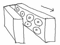
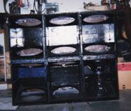
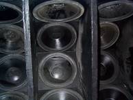
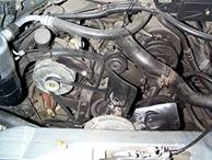
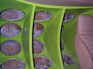
GMC Sound Pressure Level Competition Van Sound level competition became a hobby and a personal drive during employment at Carl’s Stereo on Wheels. The van was purchase one year prior, as a rehabilitation project and daily driver. A new engine and interior, including seats and carpet, was installed for reliability and personal enjoyment. The competition conversion was initiated following a conversation with Carl, company owner, regarding possible arrangement for an intense product representation and competition vehicle for the company’s customers and employees. The Installation labor and supply cost was arranged to be my responsibility. Stereo equipment, including speakers, wire, connectors, alternators, amplifiers, batteries, radio, and extras was provided by Carl. S.P.L. conversion for the van lasted more than one year; this was a period of time requiring intense personal sacrifices and creative personal best. The initial steps of the process involved an intense educational process that lasted the complete dedicated era. Different enclosures provided a plethora of enlightening experiences. Each new experience provided new possible creative ideas which sometimes lead to a new enclosure design The initial design utilized sixteen fifteen-inch MTX subwoofers, eight MTX seven-hundred watt amplifiers, and eight yellow top Optima batteries. The enclosure provided an intense free air, doors open, high pressure sound vehicle. The resonant frequency was recorded to be approximately 80Hz. The van was entered into its first sound pressure level (S.P.L) competition and was rewarded a first place trophy and money order of two-hundred fifty dollars. The van provided a pressure recording of 158 db, during the contest, off the windshield, with the doors closed. This experience provided an accouchement to an intense drive for the highest sound pressure possible. Analysis of the first enclosure, through trial and error, provided results regarding pressure cancellation. The sideways “V” configuration in picture 1, with eight subs on each arm of the “V” with four apposing the accompanying four allowed for an efficient way to install all sixteen into the van, perpendicular to the automobile floor. Enclosure construction utilized medium density fiberboard (M.D.F), fiberglass resin, and fiberglass mat. My analysis provided information that cancellation occurs with the front eight subwoofers. The rear eight connected individually, without the front eight and with only 4 amplifiers, provided the same S.P.L results recorded at the competition. I understood that the speaker enclosure would be useless if the enclosed space allowed for more than two speakers deep. Stopping examination at this point would only provide a theory without proof.
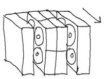
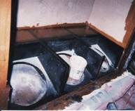
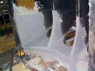
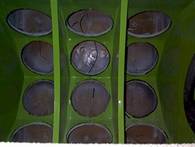
A new enclosure was the only way to provide proof for my analysis. The second enclosure design accreted from analysis of other competition vehicles and my personal experiences. The new design was similar to a “UU” shape on its side with four speakers on each arm of the “U”, perpendicular to the auto floor. Picture 2 provides some insight to the duel “U” design. This enclosure provided enough space for sixteen subwoofers to be installed behind the door jambs and eight amplifiers. Each center single subwoofer had an individual enclosure, 1.5 cubic foot, for easy speaker removal. Depth between the front of the center enclosures and the edge enclosures was only ten inches. The distance further provided additional problems with pressure cancellation. Removal of the center enclosures, provided a single wider “U” shape on its side, proved to allow for a slightly higher S.P.L than the original “V” enclosure due to the shorter travel distance for the reflection off of the rear of the enclosure. The adequate resonant frequency resulted in 80Hz, the same as the “V” enclosure. Further investigation resulted in additional information that the flat portion of the rear of the enclosure and a wide distance between apposing speakers provide increase reduction in sound cancellation. The new enclosure did not provide the desired increase in sound pressure and did not allow for the preferred amount of electronic equipment. An additional, third, enclosure must be designed for more equipment and pressure increase.
The third enclosure design provided mounting locations for only twelve fifteen-inch subwoofers and six amplifiers. A “U” enclosure design was configured to allow the subwoofers to be mounted above and below each other with six on the top “U” arm and six on the bottom “U” arm, horizontally mounted to the auto floor. The rear of the enclosure was designed to have a flat reflective surface. Opposing speakers had ample distance from each other and apposing was no further than two deep. Completion of this enclosure provided an increase in pressure recording. Further enhancement investigation loosened hidden important information about side to side apposing separation applied to more than distance from the microphone. Dividing the enclosure in to three separate “U” enclosures side by side provided a decrease in sound cancellation. The enclosure provided a recorded S.P.L. competition score of 164 db. This pressure level allowed the vehicle to place a third position at the local S.P.L. final competition. This enclosure provided its highest pressure recording at 82Hz with the rear of the enclosure located at approximately 72 inches from the microphone. During the competition, I noticed that the first and second place competitors provided a higher frequency to their vehicle during the competition. I confronted them with questions regarding their frequency analysis experience. One of the competitors informed me that the resonant frequency change was able to be changed with enclosure volume size. An additional competitor allowed the information that his competition auto can respond to individual and both 80Hz and 120Hz frequency range. I took this important information and analyzed every connection and configuration of their vehicles. The automobiles had similar enclosures with obvious pressure cancellation issues that were experienced with my enclosures.
A personal drive initiated an additional enclosure with six “V” shaped enclosures. Each “V” shaped enclosure had only one subwoofer inverted on each arm, horizontally mounted speaker cone to the automobile floor. The enclosure was installed directly behind the door jambs. The center six enclosures had useful design aspect to allow for separate enclosure removal and speaker replacement. Each enclosure supplied the desired 1.5 cubic-foot enclosure for individual speakers. This enclosure was derived from the allowance for possible decrease in pressure cancellation due to the decrease in speaker apposition. Pressure results decreased due to the use of 80Hz frequency spectrum. The decrease in S.P.L was not understood at the time. This enclosure adsorbed a large amount of time and was not providing desired results. My analysis informed me that the distance from the microphone to the rear of the enclosure must be in the range of 72 inches. Destruction of the supposed perfect enclosure happened prematurely.
Enclosure officially numbered five, not including the redesigns of the previous enclosures, allowed for the creation of a three half polygon enclosure that could be installing at a varied distance from the microphone for testing. The enclosure allowed sufficient mounting locations for twelve subwoofers and six amplifiers. Each subwoofer cone was mounted at a 45º parallel to the auto floor. Each of the straight portions of the polygon arms had two subwoofers mounted perpendicular to the windshield. Design of the enclosure came about from analysis of the first place competitor of the local S.P.L. competition. Considering that his enclosure build had a low amount of cancellation issues than all of the other competitor enclosures, he also had a very high pressure result. His enclosure had fifteen subwoofers, with five in each half polygon shape. Number five enclosure only provided four subwoofers in each half polygon to reduce pressure cancellation. Experimentation with this versatile enclosure provided answers to a variety of questions. Enclosure distance from the windshield, microphone, for 80Hz and 120Hz was solved. At 80Hz, each of the twelve separate enclosure size seemed to be prevalent at 1.5 cubic-feet with the reflective rear of the enclosure located at 72 inches. The 120Hz response prevailed when each of the individual twelve subwoofer enclosure was provided with a very small amount of air. Each of the 120Hz enclosures responded with higher S.P.L. when the enclosure was decreased as it was further from the microphone. The optimal distance of the enclosure reflective rear, for higher frequencies, was directly behind, allowed distance, the door jamb. This enclosure provided new information about resonant frequency response due to enclosure size, distance from microphone, fiberglass resin and mat use, and a final lesson which allowed for an increase of over 5db. The increase for over 5db was provided due to sealing the air circulation system of the vehicle and lining the interior of the vehicle with M.D.F. and fiberglass resin. AIR TIGHT!!!!! Following the air tight revolution the van created a ground-breaking pressure recording of 172db. I broke the 170db mark with 120Hz resonance frequency!!!
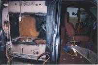
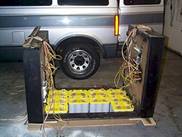
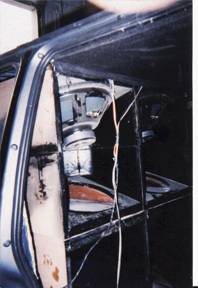
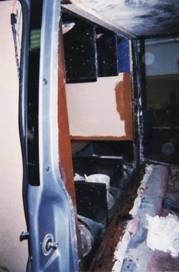
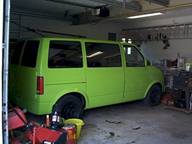
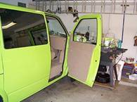
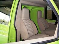
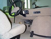
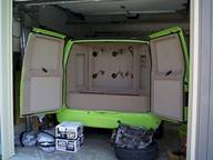
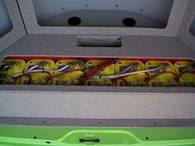
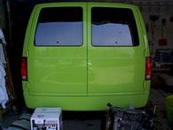
After the completion of the vehicle, new information was introduced to me about the competition rules. The 120Hz range was not acceptable due to the lack of rumble for the spectators. After the disappointment subsided, I change the enclosure and concerted it to a rumbling and loud sales vehicle that played a variety of music. The conversion process included an experience with body work and paint which is information for a different story. The final pictures of the van without equipment are located below.
Completion of the 120Hz enclosure provided important information which could have allowed the six “V” enclosures to surpass all of the other designs. I did not receive addition opportunities to critique the design for optimization. The next sealed S.P.L competition enclosure for fifteen-inch subwoofers will be a similar reproduction of the six-V at the correct distance for the frequency and enclosure air space size.
|
/Bondo%20Box.BMP)
|

/dcp00066.jpg)
/dcp00070.jpg)
/dcp00092.jpg)
/dcp00377.jpg)
/dcp00743.jpg)
/dcp00744.jpg)
/dcp00745.jpg)
/dcp00746.jpg)
/dcp00757.jpg)
/dcp00759.jpg)
/dcp00761.jpg)
/dcp00762.jpg)
/dcp00763.jpg)
/img.jpg)
/img_0001.jpg)
/img_0002.jpg)
/Sub%20Box%20Front.BMP)