- Measure voltage between the MAP sensor 3P connector terminals No. 2 and No. 3.
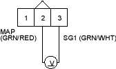
Is there about 5 V?
YES |
- Replace the MAP sensor. |
NO |
- Repair open in the wire between the ECM/PCM (A19) and the MAP sensor. |

- Turn the ignition switch OFF.
- Disconnect the MAP sensor 3P connector.
- Turn the ignition switch ON (II).
- Measure voltage between ECM/PCM connector terminals A11 and A19.
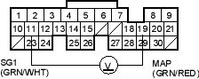
Is there about 5 V?
YES |
- Replace the MAP sensor. |
NO |
- Go to step 17. |
- Measure voltage between the MAP sensor 3P connector terminals No. 1 and body ground.
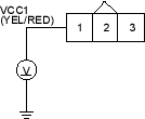
Is there about 5 V?
YES |
- Go to step 18. |
NO |
- Repair open in the wire between the ECM/PCM (A21) and the MAP sensor. |
- Turn the ignition switch OFF.
- Disconnect ECM/PCM connector A (31P).
- Check for continuity between ECM/PCM connector terminal A19 and body ground.
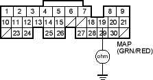
Is there continuity?
YES |
- Repair short in the wire between the ECM/PCM (A19) and the MAP sensor. |
NO |
- Substitute a known-good ECM/PCM and recheck. If symptom/indication goes away, replace the original ECM/PCM. |

