Fuel and Emissions Systems
|
11-475 |
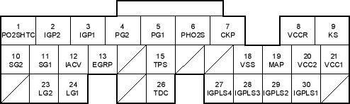
ECM/PCM Inputs and Outputs at Connector A (31P)
Wire side of female terminals
NOTE: Standard battery voltage is 12 V.
|
Terminal number |
Wire colour |
Terminal name |
Description |
Signal |
|
19 |
GRN/RED |
MAP (MANIFOLD ABSOLUTE PRESSURE (MAP) SENSOR) |
Detects MAP sensor signal |
With ignition switch ON (II): about 3 V At idle: about 1.0 V (depending on engine speed) |
|
20 |
YEL/BLU |
VCC2 (SENSOR VOLTAGE) |
Provides sensor voltage |
With ignition switch ON (II): about 5 V With ignition switch OFF: about 0 V |
|
21 |
YEL/RED |
VCC1 (SENSOR VOLTAGE) |
Provides sensor voltage |
With ignition switch ON (II): about 5 V With ignition switch OFF: about 0 V |
|
23 |
BRN/YEL |
LG2 (LOGIC GROUND) |
Ground for the ECM/PCM circuit |
Less than 1.0 V at all times |
|
24 |
BRN/YEL |
LG1 (LOGIC GROUND) |
Ground for the ECM/PCM circuit |
Less than 1.0 V at all times |
|
26 |
GRN |
TDC (TOP DEAD CENTRE (TDC) SENSOR) |
Detects TDC sensor |
With engine running: pulses |
|
27 |
BRN |
IGPLS4 (No. 4 IGNITION COIL PULSE) |
Drives No. 4 ignition coil |
With ignition switch ON (II): about 0 V With engine running: pulses |
|
28 |
WHT/BLU |
IGPLS3 (No. 3 IGNITION COIL PULSE) |
Drives No. 3 ignition coil | |
|
29 |
BLU/RED |
IGPLS2 (No. 2 IGNITION COIL PULSE) |
Drives No. 2 ignition coil | |
|
30 |
YEL/GRN |
IGPLS1 (No. 1 IGNITION COIL PULSE) |
Drives No. 1 ignition coil |
*1: with TWC model
*2: without TWC model
*3: A/T

