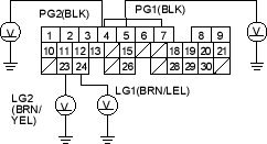
- Measure voltage between body ground and ECM/PCM connector terminals A4, A5, A23 and A24 individually.
Is there less than 1.0 V?
YES |
- Repair open in the wire (s) between that had more than 1.0 V between G101 and ECM/PCM (A4, A5, A23, A24). |
NO |
- Go to step 48. |

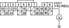
- Measure voltage between body ground and ECM/PCM connector terminal A21.
Is there about 5 V?
YES |
- Go to step 55. |
NO |
- Go to step 49. |
- Turn the ignition switch OFF.
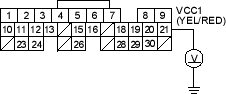
- Disconnect the MAP sensor 3P connector one at a time, and measure voltage between body ground and ECM/PCM connector terminal A21 with the ignition switch ON (II).
Is there about 5 V?
YES |
- Replace the MAP sensor. |
NO |
- Go to step 51. |
- Turn the ignition switch OFF.
- Disconnect the MAP sensor 3P connector.
- Disconnect ECM/PCM connector A (31P)

