DTC P0113: IAT Sensor Circuit High Voltage
- Turn the ignition switch ON (II).
- Check the IAT with the scan tool.
Is -20°C (-4°F) or less (or L-Limit in Honda mode of PGM Tester) or 5 V indicated?
YES |
- Go to step 3. |
NO |
- Intermittent failure, system is OK at this time. Check for poor connections or loose wires at the IAT sensor and at the ECM/PCM. |

- Turn the ignition switch OFF.
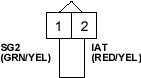
- Disconnect the IAT sensor 2P connector.
- Connect the IAT sensor 2P connector terminals No. 1 and No. 2 with a jumper wire.
- Turn the ignition switch ON (II).
- Check the IAT with the scan tool.
Is -20°C (-4°F) or less (or L-Limit in Honda mode of PGM Tester) or 5 V indicated?
YES |
- Go to step 8. |
NO |
- Replace the IAT sensor. |
- Turn the ignition switch OFF.
- Remove the jumper wire.
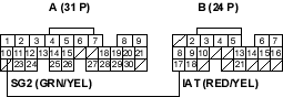
- Connect ECM/PCM connector terminals A10 and B17 with a jumper wire.
- Turn the ignition switch ON (II).
- Check the IAT with the scan tool.
Is -20°C (-4°F) or less (or L-Limit in Honda mode of PGM Tester) or 5 V indicated?
YES |
- Substitute a known-good ECM/PCM and recheck (see page 11-6). If symptom/indication goes away, replace the original ECM/PCM. |
NO |
- Repair open in the wire between the ECM/PCM (A10, B17) and the IAT sensor. |

