DTC P0122: TP Sensor Circuit Low Voltage
- Turn the ignition switch ON (II).
- Check the throttle position with the scan tool.
Is there about 10% or 0.5 V when the throttle is fully closed and about 90% or 4.5 V when the throttle is fully opened?
YES |
- Intermittent failure, system is OK at this time. Check for poor connections or loose wires at the TP sensor and at the ECM/PCM. |
NO |
- Go to step 3. |

- Turn the ignition switch OFF.
- Disconnect the TP sensor 3P connector.
- Turn the ignition switch ON (II).
- Measure voltage between the TP sensor 3P connector terminals No. 1 and No. 3.
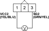
Is there about 5 V?
YES |
- Go to step 7. |
NO |
- Go to step 14. |
- Turn the ignition switch OFF.
- At the sensor side, measure resistance between the TP sensor 3P connector terminals No. 1 and No. 3 with the throttle fully closed.
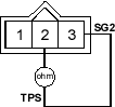
Is there about 0.5-0.9 k ohms?
YES |
- Go to step 9. |
NO |
- Replace the throttle body. |
- Measure resistance between the TP sensor 3P connector terminals No. 1 and No. 2 with the throttle fully closed.
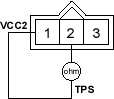
Is there about 4.5k ohms?
YES |
- Go to step 10. |
NO |
- Replace the throttle body. |
- Disconnect ECM/PCM connector A (31P).

