- Remove the transmission range switch harness connector (A) from the connector bracket (B), then disconnect the connector.
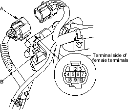
Connector Terminal Description
| No. | Description | No. | Description |
| 1 | GND | 6 |  |
| 2 | Not used | 7 |  |
| 3 | ATP NP | 8 |  |
| 4 |  |
9 |  |
| 5 | Not used | 10 |  |
- Check for continuity between terminals at the harness connector. There should be continuity between the terminals listed for each switch position.
In position, between terminals:
- No. 1 and No. 3
- No. 1 and No. 8
- No. 3 and No. 8
In position, between terminals:
- No. 1 and No. 9
In position, between terminals:
- No. 1 and No. 3
- No. 1 and No. 10
- No. 3 and No. 10
In position, between terminals:
- No. 1 and No. 4
In position, between terminals:
- No. 1 and No. 6
In position, between terminals:
- No. 1 and No. 7
- If there is no continuity between any terminal, remove the transmission range switch cover and disconnect the connector (A) at the switch (B).
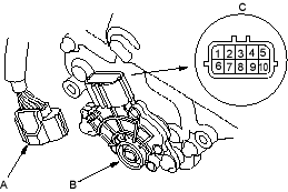
Connector Terminal Description
| No. | Description | No. | Description |
| 1 | |
6 | |
| 2 | |
7 | |
| 3 | |
8 |  |
| 4 | GND | 9 | Not used |
| 5 | ATP NP | 10 | Not used |
- Check for continuity between terminals at the switch connector (C). There should be continuity between the terminals listed for each position.
In position, between terminals:
- No. 4 and No. 5
- No. 4 and No. 6
- No. 5 and No. 6
In position, between terminals:
- No. 1 and No. 4
In position, between terminals:
- No. 4 and No. 5
- No. 4 and No. 7
- No. 5 and No. 7
In position, between terminals:
- No. 2 and No. 4
In position, between terminals:
- No. 4 and No. 8
In position, between terminals:
- No. 3 and No. 4
- If there is no continuity between any terminals, check the transmission range switch installation. If the transmission range switch installation is OK, replace the switch.
- If the transmission range switch continuity check was OK, replace the faulty transmission range switch harness.

