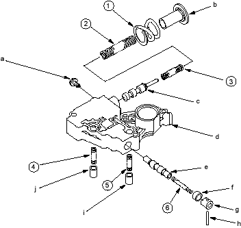
Valve Body

Regulator Valve Body Disassembly, Inspection and Reassembly

14-186  

  1. Clean all parts thoroughly in solvent or carburettor cleaner and dry them with compressed air. Blow out all passages.
  2. Do not use a magnet to remove the cooler relief valve (ball), it may magnetise the valve (ball).
  3. Check all valves for free movement. If any fail to slide freely, refer to Valve Body Repair (see page 14-181).
  4. Replace the valve body as an assembly if any parts are worn or damaged.
  5. Hold the regulator spring cap in place while removing the stop bolt. The regulator spring cap is spring loaded. Once the stop bolt is removed, release the spring cap slowly so it does not pop out.
  6. Reassembly is the reverse of the disassembly.
  7. Coat all parts with ATF during assembly.
  8. Align the hole in the regulator spring cap with the hole in the valve body, then press the spring cap into the valve body and tighten the stop bolt.
    1. STOP BOLT

      6 x 1.0 mm, 12 Nm (1.2 kgf/m, 8.7 lbf/ft)

    2. REGULATOR SPRING CAP
    3. REGULATOR VALVE
    4. REGULATOR VALVE BODY

      Inspect for scoring and damage)

    5. LOCK-UP CONTROL VALVE
    6. VALVE SLEEVE
    7. VALVE CAP
    8. ROLLER
    9. TORQUE CONVERTER CHECK VALVE
    10. COOLER RELIEF VALVE (BALL)

SPRING SPECIFICATIONS

No. Spring Standard (New)-Unit: mm (in.)
    Wire Dia. O.D. Free Length No. of Coils
(1) Stator reaction spring 4.5 (0.177) 35.4 (1.394) 30.3 (1.193) 1.9
(2) Regulator valve spring A 1.9 (0.075) 14.7 (0.579) 77.4 (3.047) 15.2
(3) Regulator valve spring B 1.8 (0.071) 9.6 (0.378) 44.0 (1.732) 12.6
(4) Cooler relief valve spring 1.0 (0.039) 8.4 (0.331) 33.8 (1.331) 8.2
(5) Torque converter check valve spring 1.0 (0.039) 8.4 (0.331) 33.8 (1.331) 8.2
(6) Lock-up control valve spring 0.8 (0.031) 6.0 (0.236) 38.4 (1.512) 30.3