- Measure the clearance between the 25 x 31 mm thrust shim (A) and the snap ring (B) with a feeler gauge (C).
NOTE: Take measurements in at least 3 places and use the average as the actual clearance.
STANDARD: 0.05-0.115 mm (0.018-0.030 in.)
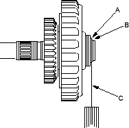
- If the clearance is out of standard, remove the 25 x 31 mm thrust shim (A) and measure its thickness.
- Select and install the new thrust shim and secure them with the snap ring, then recheck.
THRUST SHIM, 25 x 31 mm
| No. | Part Number | Thickness |
| A | 90451-P4V-000 | 1.05 mm (0.041 in.) |
| B | 90452-P4V-000 | 1.12 mm (0.044 in.) |
| C | 90453-P4V-000 | 1.19 mm (0.047 in.) |
| D | 90454-P4V-000 | 1.26 mm (0.050 in.) |
| E | 90455-P4V-000 | 1.33 mm (0.052 in.) |
| F | 90456-P4V-000 | 1.40 mm (0.055 in.) |
| G | 90457-P4V-000 | 1.47 mm (0.058 in.) |
| H | 90458-P4V-000 | 1.54 mm (0.061 in.) |
| I | 90459-P4V-000 | 1.61 mm (0.063 in.) |
| J | 90460-P4V-000 | 1.68 mm (0.066 in.) |
| K | 90461-P4V-000 | 1.75 mm (0.069 in.) |
| L | 90462-P4V-000 | 1.82 mm (0.072 in.) |
| M | 90480-P4V-000 | 1.085 mm (0.0427 in.) |
| N | 90481-P4V-000 | 1.155 mm (0.0454 in.) |
| O | 90482-P4V-000 | 1.225 mm (0.0482 in.) |
| P | 90483-P4V-000 | 1.295 mm (0.0510 in.) |
| Q | 90484-P4V-000 | 1.365 mm (0.0537 in.) |
| R | 90485-P4V-000 | 1.435 mm (0.0565 in.) |
| S | 90486-P4V-000 | 1.505 mm (0.0593 in.) |
| T | 90487-P4V-000 | 1.575 mm (0.0620 in.) |
| U | 90488-P4V-000 | 1.645 mm (0.0648 in.) |
| V | 90489-P4V-000 | 1.715 mm (0.0675 in.) |
| W | 90490-P4V-000 | 1.785 mm (0.0703 in.) |
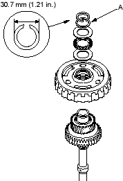
- After replacing the 25 x 31 mm thrust shim, make sure that the clearance is within tolerance.
- Verify that the snap ring outside diameter is 30.7 mm (1.21 in.) or less.

