Special Tools Required
- DLC terminal box, 07WAJ-0010100
- SCS short connector, 07PAZ-0010100
When the PCM senses an abnormality in the input or output systems, the  indicator light in the gauge assembly will usually blink and/or the MIL may come on. When the 16P Data Link Connector (DLC) (located under the dash behind the centre console) is connected with the special tool (DLC terminal box), or when the Service Check Connector (2P) (located under the dash behind the centre console) is connected with the special tool (SCS Short Connector), the indicator light will blink the Diagnostic Trouble Code (DTC) when the ignition switch is turned ON (II).
4-door Model:
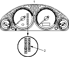
- GAUGE ASSEMBLY
- INDICATOR LIGHT
5-door Model:
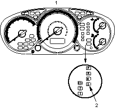
- GAUGE ASSEMBLY
- INDICATOR LIGHT
indicator light has been reported on;
- Connect the 16P Data Link Connector with the special tool (DLC terminal box), then connect the jumper wire between the terminals 4 and 9 at the special tool. Turn the ignition switch ON (II), then observe the indicator light.
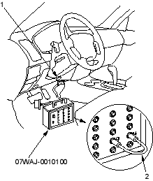
- 16P DATA LINK CONNECTOR
- JUMPER WIRE
- Connect the Service Check Connector (2P) with the special tool (SCS Short Connector). Turn the ignition switch ON (II), then observe the indicator light.
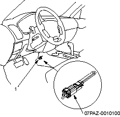
- SERVICE CHECK CONNECTOR

