Automatic Transmission
System description (cont'd)
|
14-65 |
|
Lock-up System
In  position (3rd and 4th) and
  position (3rd), pressurised fluid is drained from the back of the torque converter through a fluid passage, causing the lock-up piston to be held against the torque converter cover. As this takes place, the mainshaft rotates at the same speed as the engine crankshaft. Together with hydraulic control, the PCM optimises the timing of the lock-up mechanism. When the torque converter clutch solenoid valve activates, modulator pressure changes to switch lock-up on and off. The lock-up control valve and the lock-up timing valve control the range of the lock-up according to A/T clutch pressure control solenoid valve B. The torque converter clutch solenoid valve is mounted on the torque converter housing and A/T clutch pressure control solenoid valve B is mounted on the transmission housing with solenoid valve A as an assembly. They are all controlled by the PCM.
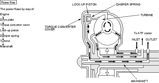
Lock-up Clutch ON (Engaging Lock-up Clutch)
Fluid in the camber between the torque converter cover and the lock-up clutch piston is drained off and fluid entered from the chamber between the pump and stator exerts pressure through the lock-up clutch piston against the torque converter cover. The lock-up clutch piston engages with the torque converter cover (lock-up clutch ON) and the mainshaft rotates at the same speed as the engine.
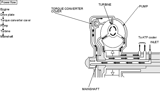
Lock-up Clutch OFF (Disengaging Lock-up Clutch)
Fluid entered from the chamber between the torque converter cover and the lock-up clutch piston passes through the torque converter and goes out from the chambers between the turbine and the stator and between the pump and the stator. As a result, the lock-up clutch pistoNmoves away from the torque converter cover and the lock-up clutch is released (lock-up clutch OFF).