Automatic Transmission
|
14-67 |
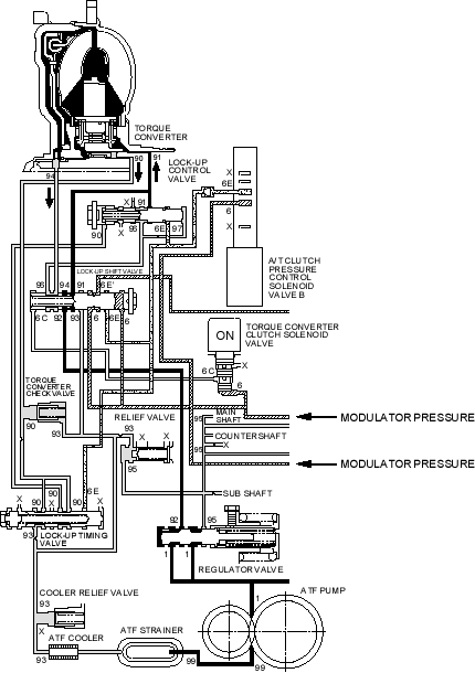
Partial Lock-up
As the speed of the vehicle reaches the prescribed value, the torque converter clutch solenoid valve is turned ON by the PCM. Modulator (LC A) pressure (6C) in the left side of the lock-up shift valve is released and the lock-up shift valve is moved to the left side to switch the port leading torque converter pressure (91) to the right side of the torque converter. Torque converter pressure (91) flows to the right side of the torque converter to engage the lock-up clutch. The PCM also controls the A/T clutch pressure control solenoid valve B and linear sol B pressure (6E) is applied to the lock-up control valve and the lock-up timing valve. The positions of the lock-up control valve and lock-up timing valve depend on torque converter pressure and linear sol B pressure. When linear sol B pressure (6E) is low, torque converter pressure (91) from the lock-up shift valve to the right side of the torque converter is low, because torque converter pressure (91) leaks at the lock-up control valve. The lock-up clutch is engaged partially. Linear solenoid B pressure (6E) increases, the lock-up control valve is moved to the left side to cover the port draining torque converter pressure (91) and torque converter pressure (91) to torque converter is increased. The engagement of the lock-up clutch depends on torque converter pressure (91).
NOTE: When used, ''left'' or ''right'' indicates direction on the hydraulic circuit.

