- Disconnect the gauge assembly connector B (22P), and go to step 10 for 4-door model. Disconnect the gauge assembly connector A (22P) and go to step 12 for 5-door model.
- Check for continuity between the gauge assembly connector B (22P) terminal No. 15 and body ground.
GAUGE ASSEMBLY CONNECTOR B (22P)
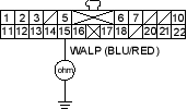
Wire side of female terminals
Is there continuity?
YES - Repair short to body ground in the wire between the gauge assembly and the ABS control unit. 
NO - Go to step 11.
- Check for continuity between the gauge assembly connector B (22P) terminal No. 18 and body ground.
GAUGE ASSEMBLY CONNECTOR B (22P)
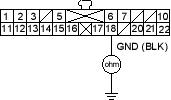
Wire side of female terminals
Is there continuity?
YES - Check for loose terminals in the gauge assembly connectors. If the connectors are OK, replace the gauge assembly.
NO - Repair open in the wire between the gauge assembly and body ground (G501).
- Check for continuity between the gauge assembly connector A (22P) terminal No. 12 and body ground.
GAUGE ASSEMBLY CONNECTOR B (22P)
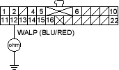
Wire side of female terminals
Is there continuity?
YES - Repair short to body ground in the wire between the gauge assembly and the ABS control unit.
NO - Go to step 13.
- Check for continuity between the gauge assembly connector B (22P) terminal No. 12 and body ground.
GAUGE ASSEMBLY CONNECTOR B (22P)
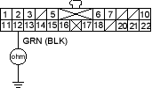
Wire side of female terminals
Is there continuity?
YES - Check for loose terminals in the gauge assembly connectors. If the connectors are OK, replace the gauge assembly.
NO - Repair open in the wire between the gauge assembly and body ground (G501).

