ABS Components
|
19-62 |
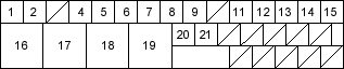
ABS Control Unit Inputs and Outputs for 31P Connector
Wire side of female terminals
| Terminal
number |
Wire colour | Terminal sign
(Terminal name) |
Description | Measurement | |||
| Terminals | Conditions (Ignition
switch ON (II)) |
Voltage | |||||
| 1 | BLU/YEL | RRS (-)
Rear-right signal negative) |
Detects right-rear wheel sensor signal | 1 – 2 | Wheel | Spin wheel at 1 turn/second |
AC: 0.053V or above
Oscilloscope 0.15 Vp-p or above |
| 2 | GRN/YEL | RRS (+)
(Rear-right signal positive) |
|||||
| 4 | BLU | FRS (-)
(Front-right signal negative) |
Detects right-front wheel sensor signal | 4 – 5 | |||
| 5 | GRN/DLK | FRS (+)
(Front-right signal positive) |
|||||
| 6 | BRN/WHT | FLS (-)
(Front-left signal negative) |
Detects left-front wheel sensor signal | 6 – 7 | |||
| 7 | BLU/ORN | FLS (+)
(Front-left signal positive) |
|||||
| 8 | GRY/RED | RLS (-)
(Rear-left signal positive) |
Detects left-rear wheel sensor signal | 8 – 9 | |||
| 9 | YEL/RED | RLS (+)
(Rear-Left signal positive) |
Stops | About 2.5 V | |||
| 11 | LT BLU | DIAG – K
(Diagnosis K) |
Communicates with the Honda PGM Tester | ——— | ——— | ——— | |
| 12 | BRN | DIAG –
(Diagnosis L) |
DTC indication | ——— | ——— | ——— | |

