- Measure the resistance between the appropriate wheel sensor (+) and ( - ) circuit terminals (see table).
| DTC | Appropriate Terminal | |
| (+) Side | (-) Side | |
| 12 (Right-front) | No. 5: FRS (+) | No. 4: FRS (+) |
| 14 (Left-front) | No. 7: FLS (+) | No. 6: FLS (+) |
| 16 (Right-rear) | No. 2: RRS (+) | No. 1: RRS (+) |
| 18 (Left-rear) | No. 9: RLS (+) | No. 8: RLS (+) |
ABS CONTROL UNIT 31P CONNECTOR
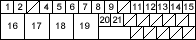
Wire side of female terminals
Is there less than 450 ohms?
YES - Repair short to wire between the appropriate wheel sensor (+) and (-) circuits. 
NO - Go to step 4.
- Check for continuity between the appropriate wheel sensor (+) circuit terminal and other wheel sensor (+) circuit terminals (see table).
DTC Appropriate Terminal Other Terminal 12 No. 5: FRW (+) No. 7 No. 2 No. 9 14 No. 7: FLW (+) No. 5 No. 2 No. 9 16 No. 2: RRW (+) No. 5 No. 7 No. 9 18 No. 9: RLW (+) No. 5 No. 7 No. 2
Is there continuity?
YES - Repair short in the wire between the appropriate wheel sensor and the other wheel sensor harnesses.
NO - Clear the DTC, and test-drive the vehicle. If the ABS indicator comes on and the same DTC is indicated, replace the ABS modulator-control unit.
- Clear the DTC.
- Test-drive the vehicle at 19 mph (30 km/h) or more.
Does the ABS indicator come on and is DTC 21 indicated?
YES - Go to step 3.
NO - The system is OK at this time.
- Check the pulsar gear for a chipped tooth.
Is the pulsar OK?
YES - Check for loose ABS control unit 31P connector. If necessary, substitute a known-good ABS modulator-control unit and recheck.
NO - Replace the driveshaft or hub unit. (Chipped pulsar gear).

