- Turn the ignition switch ON (II).
- Connect the ABS control unit 31P connector terminal No. 20 and body ground with a jumper wire.
ABS CONTROL UNIT 31P CONNECTOR
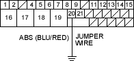
Wire side of female terminals
Does the ABS indicator go off?
YES - Check for loose terminals in the ABS control unit 31P connector. If necessary, substitute a known-good ABS modulator-control unit and recheck. 
NO - Go to step 11 for 4-door model. Go to step 12 for 5-door model.
- Connect the gauge assembly connector B (22P) terminal No. 15 and body ground with a jumper wire.
GAUGE ASSEMBLY CONNECTOR B (22P)
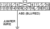
Wire side of female terminals
Does the ABS indicator go off?
YES - Repair open in the wire between the gauge assembly and the ABS control unit.
NO - Check for a loose gauge assembly connector B (22P). If the connector is OK, replace the printed circuit board in the gauge assembly.
- Connect the gauge assembly connector A (22P) terminal No. 12 and body ground with a jumper wire.
GAUGE ASSEMBLY CONNECTOR A (22P)
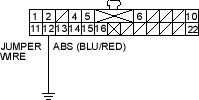
Wire side of female terminals
Does the ABS indicator go off?
YES - Repair open in the wire between the gauge assembly and the ABS control unit.
NO - Check for loose gauge assembly connector A (22P). If the connector is OK, replace the gauge assembly.

