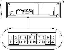
| Wire | Connects to | |
| 1*¹ | YEL/GRN | Roof antenna |
| 2 | YEL/RED | ACC (Main stereo power supply) |
| 3 | ——— | Not used |
| 4*² | RED/WHT | Security signal input |
| 5 | PNK | Right rear[door]speaker (+) |
| 6 | BLU/WHT | Left rear [door] speaker (+) |
| 7 | GRN/YEL | Right front door speaker (+) |
| 8 | GRN/BLK | Left front door speaker (+) |
| 9 | RED/BLK | Lights - on signal |
| 10 | WHT/RED | Constant power |
| 11 | ——— | Not used |
| 12 | ——— | Not used |
| 13 | ——— | Not used |
| 14 | ——— | Not used |
| 15 | BLU/YEL | Right rear [door] speaker ( – ) |
| 16 | BLU/BLK | Left rear [door] speaker ( – ) |
| 17 | GRY/RED | Right front door speaker ( – ) |
| 18 | LT GRN | Left front door speaker ( – ) |
| 19*³ | RED | Dash lights brightness controller |
| 20 | BLK | Ground (G503) |
[ ]: 5-door
*1: 5-door with roof antenna
*2: With security alarm system
*3: With dash lights brightness controller
AUDIO UNIT 20P CONNECTOR
- Put on gloves to protect your hands.
- Take care not to scratch the dashboard and related parts.
- Make sure you have the anti-theft code for the radio, then write down the frequencies for the radio's preset buttons.
- Remove the dashboard centre lower cover (see page 20-77).
- Remove the heater control panel (or climate control unit) (see page 21-51) from the centre panel.
- Remove the four mounting bolts and the audio unit from the radio brackets.
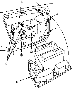
- Install the audio unit in the reverse order of removal and note these items:
- Make sure the audio unit and A/C connectors are plugged in properly and the antenna lead is connected properly.
- Enter the anti-theft code for the radio, then enter the customer's radio station presets.

