Alternator Control System Test (KU, KT, KX, KK models)
- Check for proper operation of the ELD by checking the MIL 4-door (see page 11-3) or 5-door (see page 11-309).
- Disconnect the alternator 4P connector from the alternator.
- Start the engine, and turn the headlights (high beam) ON.
- Measure voltage between the alternator 4P connector terminal No. 2 and the positive terminal of the battery.
BATTERY
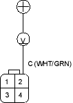 ALTERNATOR 4P CONNECTOR
Wire side of female terminals
Is there 1 V or less?
YES - Go to step 8.
NO - Go to step 5.
- Turn the headlight and ignition switch OFF.
- Disconnect ECM/PCM connector B (24P).
- Check for continuity between ECM/PCM connector terminal B18 and body ground.
ECM/PCM CONNECTOR B (24P)
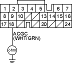 Wire side of female terminals
Is there continuity?
YES - Repair short in the wire between the alternator and ECM/PCM. 
NO - Substitute a known-good ECM/PCM, and recheck (see page 11-3) or 5-door (see page 11-309). If prescribed voltage is now available, replace the original ECM/PCM.
- Turn the headlight and ignition switch OFF.
- Disconnect ECM/PCM connector B (24P).
- Check for continuity between ECM/PCM connector terminal B18 and alternator 4P connector terminal No. 2.
ECM/PCM CONNECTOR B (24P)
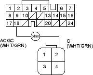 ALTERNATOR 4P CONNECTOR
Wire side of female terminals
Is there continuity?
YES - Repair the alternator (see page 4-32).
NO - Repair open in the wire between the alternator and ECM/PCM.

