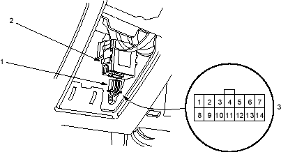
- 14P CONNECTOR
- CRUISE CONTROL UNIT
- Wire side of female terminals
Cruise Control
|
4-44 |
SRS components are located in this area. Review the SRS component locations (see page 23-25), precautions and procedures (see page 23-25) in the SRS before performing repairs or service.
|
|
|
| Cavity | Wire | Test condition | Test: Desired result | Possible cause if result is not obtained |
| 1 | BRN/WHT | Connect battery power | Check the operation of the magnetic clutch: Clutch should click and output link should be locked. |
|
| 2 | BLU | Ignition switch ON (II), main switch ON and brake pedal pressed, then released | Check for voltage to ground:
There should be 0 V with the pedal pressed and battery voltage with the pedal released. |
|
| 3 | BLK | Under all conditions | Check for continuity to ground:
There should be continuity. |
|

