DTC 11: IMA Circuit Malfunction
- Reset the ECM/PCM (see page 11-168).
- Start the engine, then let it idle for more than 5 seconds.
Is the MIL on and does it indicate DTC 11?
YES |
- Go to step 3. |
NO |
- Intermittent failure, system is OK at this time. Check for poor connections or loose wires at the IMA sensor and at the ECM/PCM. |

- Turn the ignition switch OFF.
- Turn the ignition switch ON (II).
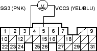
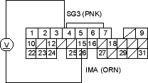
- Measure voltage between ECM/PCM connector terminals E4 and E5.
Is there about 5 V?
YES |
- Go to step 6. |
NO |
- Substitute a known-good ECM/PCM and recheck. If symptom/indication goes away, replace the original ECM/PCM. |
- Measure voltage between ECM/PCM connector terminals E4 and E15.

Is there about 0.5-4.5 V?
YES |
- Substitute a known-good ECM/PCM and recheck. If symptom/indication goes away, replace the original ECM/PCM. |
NO |
- Go to step 7. |
- Measure voltage between ECM/PCM connector terminals E4 and E15.
Is there about 5 V?
YES |
- Go to step 8. |
NO |
- Go to step 13. |
- Turn the ignition switch OFF.
- Disconnect the IMA 3P connector.
- Turn the ignition switch ON (II).
- Measure voltage between IMA 3P connector terminals No. 1 and No. 3.
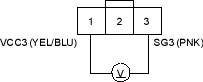
Is there about 5 V?
YES |
- Go to step 12. |
NO |
- Repair open in the wire between the ECM/PCM (E4) and the IMA. |

