Fuel and Emissions Systems
|
11-478 |
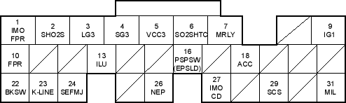
ECM/PCM Inputs and Outputs at Connector E (31P)
Wire side of female terminals
NOTE: Standard battery voltage is 12 V.
Terminal number |
Wire colour |
Terminal name |
Description |
Signal |
1*1 |
GRN/YEL |
IMO FPR (IMMOBILIZER FUEL PUMP RELAY) |
Drives PGM-FI main relay 2 |
0 V for 2 seconds after turning ignition switch ON (II), then battery voltage |
2*1 |
WHT/RED |
SHO2S (SECONDARY HEATED OXYGEN SENSOR (SECONDARY HO2S), SENSOR 2) |
Detects secondary HO2S (sensor 2) signal |
With throttle fully opened from idle with fully warmed up engine: above 0.6 V With throttle quickly closed: below 0.4 V |
3 |
BRN/YEL |
LG3 (LOGIC GROUND) |
Ground for the ECM/PCM control circuit |
Less than 1.0 V at all times |
4 |
PNK |
SG3 (SENSOR GROUND) |
Sensor ground |
Less than 1.0 V at all times |
5 |
YEL/BLU |
VCC3 (SENSOR VOLTAGE) |
Provides sensor voltage |
With ignition switch ON (II): about 5 V With ignition switch OFF: about 0 V |
6*1 |
BLK/WHT |
SO2SHTC (SECONDARY HEATED OXYGEN SENSOR (SECONDARY HO2S) HEATER CONTROL) |
Drives secondary HO2S heater |
With ignition switch ON (II): battery voltage With fully warmed up engine running: duty controlled |
7 |
RED/YEL |
MRLY (PGM-FI MAIN RELAY) |
Drives PGM-FI main relay 1 Power source for the DTC memory |
With ignition switch ON (II): about 0 V With ignition switch OFF: battery voltage |
9 |
YEL/BLK |
IG1 (IGNITION SIGNAL) |
Detects ignition signal |
With ignition switch ON (II): battery voltage With ignition switch OFF: about 0 V |
10*2 |
GRN/YEL |
FPR (FUEL PUMP RELAY) |
Drives PGM-FI main relay 2 |
0 V for 2 seconds after turning ignition switch ON (II), then battery voltage |
13*2 |
WHT/BLU |
ILU (INTERLOCK CONTROL UNIT) |
Drives interlock control unit |
With ignition switch ON (II) and brake pedal depressed: battery voltage or about 0 V |
15*2 |
ORN |
IMA (IDLE MIXTURE ADJUSTER (IMA)) |
Detects IMA signal |
With ignition switch ON (II): about 0.5-4.5 V (depending on idle mixture) |
16*1 |
LT GRN/BLK |
PSPSW (POWER STEERING PRESSURE SWITCH SIGNAL) |
Detects PSP switch signal |
At idle with steering wheel in straight ahead position: 0 V At idle with steering wheel at full lock: battery voltage |
16*2 |
LT GRN/BLK |
EPSLD (ELECTRICAL POWER STEERING LOAD DETECT) |
Detects power steering load signal |
At idle with steering wheel in straight ahead position: 0 V At idle with steering wheel at full lock: battery voltage momentarily |
18 |
RED |
ACC (A/C CLUTCH RELAY) |
Drives A/C clutch relay |
With compressor ON: about 0 V With compressor OFF: battery voltage |
22 |
WHT/BLK |
BKSW (BRAKE PEDAL POSITION SWITCH) |
Detects brake pedal position switch signal |
With brake pedal released: about 0 V With brake pedal pressed: battery voltage |
23 |
LT BLU |
K-LINE |
Sends and receives scan tool signal |
With ignition switch ON (II): pulses or battery voltage |
24 |
YEL |
SEFMJ |
Communicates with multiplex control unit |
With ignition switch ON (II): about 5 V With engine running under load: pulses |
26 |
BLU |
NEP (ENGINE SPEED PULSE) |
Outputs engine speed pulse |
With engine running: pulses |
27 |
RED/BLU |
IMOCD (IMMOBILISER CODE) |
Detects immobiliser signal |
|
29 |
BRN |
SCS (SERVICE CHECK SIGNAL) |
Detects service check signal |
With the service check signal shorted: about 0 V With the service check signal opened: about 5 V battery voltage |
31 |
GRN/ORN |
MIL (MALFUNCTION INDICATOR LAMP) |
Drives MIL |
With MIL turned ON: about 0 V With MIL turned OFF: battery voltage |
*1: with TWC model
*2: without TWC model
*3: A/T

