Honda Multi Matic Transmission/CVT
|
14-269 |
PCM Inputs and Outputs
The PCM terminal voltage and measuring conditions are shown for the connector terminals that are related to the A/T control system. The other PCM terminal voltage and measuring conditions are described in section 11.
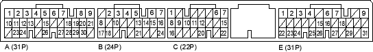
PCM Connector Terminal Locations
PCM CONNECTOR A (31P)
| Terminal Number | Wire Colour | Signal | Description | Measuring Conditions/Terminal Voltage |
| A2 | YEL/BLK | IGP2 | Power supply circuit from main relay | With ignition switch ON (II): Battery voltage
With ignition switch OFF: 0 V |
| A3 | YEL/BLK | IGP1 | Power supply circuit from main relay | With ignition switch ON (II): Battery voltage
With ignition switch OFF: 0 V |
| A4 | BLK | PG2 | Ground | |
| A5 | BLK | PG1 | Ground | |
| A10 | GRN/YEL | SG2 | Sensor ground | |
| A11 | GRN/YEL | SG1 | Sensor ground | |
| A18 | BLU/WHT | VEL2 | Vehicle speed sensor signal input | Depending on vehicle speed: Pulsing signal
When vehicle is stopped: About 0 V |
| A20 | YEL/BLU | VCC2 | Power supply for sensors | With ignition switch ON (II): 5 V
With ignition switch OFF: 0 V |
| A21 | YEL/RED | VCC1 | Power supply for sensors | With ignition switch ON (II): 5 V
With ignition switch OFF: 0 V |
| A23 | BRN/YEL | LG2 | Ground | |
| A24 | BRN/YEL | LG1 | Ground |

