Honda Multi Matic Transmission/CVT
|
14-270 |
Electronic Control System (cont'd)
PCM Inputs and Outputs
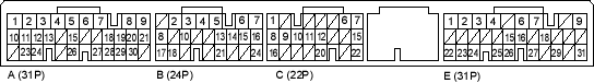
PCM Connector Terminal Location
PCM CONNECTOR B (24P)
| Terminal Number | Wire Colour | Signal | Description | Measuring Conditions/Terminal Voltage |
| B7 | GRN/WHT | HLC LSP | CVT pulley pressure control valve assembly power supply positive electrode | With ignition switch ON (II): Pulsing signal |
| B16 | YEL/GRN | SC LSP | CVT start clutch pressure control valve assembly power supply positive electrode | With ignition switch ON (II): Pulsing signal |
| B24 | BLU/WHT | SH LSP | CVT speed change control valve assembly power supply positive electrode | With ignition switch ON (II): Pulsing signal |
PCM CONNECTOR C (22P)
| Terminal Number | Wire Colour | Signal | Description | Measuring Conditions/Terminal Voltage |
| C1 | BLK/RED | HLC LSM | CVT pulley pressure control valve assembly power supply negative electrode | |
| C6 | GRN/RED | SOL INH | Inhibitor solenoid control | With inhibitor solenoid ON: Battery voltage
With inhibitor solenoid OFF: 0 V |
| C7 | RED/BLU | NDR | CVT drive pulley speed sensor signal input | In other than  and and  position: Pulsing signal position: Pulsing signal |
| C8 | BLU/RED | SC LSM | CVT start clutch pressure control valve assembly power supply negative electrode | |
| C9 | RED | ATP S | Transmission range switch  position input position input |
In position: 0 V
In other than |
| C10 | WHT | ATP R | Transmission range switch  position input position input |
In position: 0 V
In other than |
| C11 | BLU | ATP L | Transmission range switch  position input position input |
In position: 0 V
In other than |

