Automatic Transmission
|
14-47 |
PCM Inputs and Outputs
The PCM terminal voltage and measuring conditions are shown for the connector terminals that are related to the A/T control system. The other PCM terminal voltage and measuring conditions are described in section 11.
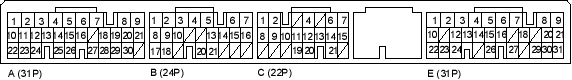
PCM Connector Terminal Locations
NOTE: The illustration shows example of connector terminal arrangement; connector terminal arrangement varies with models.
PCM CONNECTOR A (31P)
| Terminal Number | Wire Colour | Signal | Description | Measuring Conditions/Terminal Voltage |
| A2 | YEL/BLK | IGP2 | Power supply circuit from main relay | With ignition switch ON (ll): Battery voltage
With ignition switch OFF: 0V |
| A3 | YEL/BLK | IGP1 | Power supply circuit from main relay | With ignition switch ON (II): Battery voltage
With ignition switch OFF: 0 V |
| A4 | BLK | PG2 | Ground | |
| A5 | BLK | PG1 | Ground | |
| A23 | BRN/YEL | LG2 | Ground | |
| A24 | BRN/YEL | LG1 | Ground |
PCM CONNECTOR B (24P)
| Terminal Number | Wire Colour | Signal | Description | Measuring Conditions/Terminal Voltage |
| B7 | RED/BLK | LS A+ | A/T clutch pressure control solenoid valve A power supply positive electrode | With ignition switch ON (II): Pulsing signal |
| B16 | BLK/RED | LS B+ | A/T clutch pressure control solenoid valve B power supply positive electrode | With ignition switch ON (II): Pulsing signal |
| B20
(5-door) |
PNK | D3 SW | D3 switch  position input position input |
In ,  and and  positions: About 2.5 V positions: About 2.5 V
Other than |

