Automatic Transmission
|
14-48 |
Electronic Control System (cont'd)
PCM Inputs and Outputs
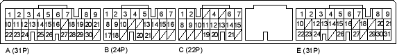
PCM Connector Terminal Locations
NOTE: The illustration shows example of connector terminal arrangement; connector terminal arrangement varies with models.
PCM CONNECTOR C (22P)
| Terminal Number | Wire Colour | Signal | Description | Measuring Conditions/Terminal Voltage |
| C1 | WHT/BLK | LS A- | A/T clutch pressure control solenoid valve A power supply negative electrode | |
| C2 | YEL/BLU | LC | Torque converter clutch solenoid valve control | During lock-up condition: Battery voltage
During no lock-up condition: 0 V |
| C4 | GRN/WHT | SH B | Shift solenoid valve B control | Battery voltage in these positions:
0 V in these positions:
|
| C6 | BLU/BLK | SH A | Shift solenoid valve A control | Battery voltage in these positions:
|
| C7 | WHT/RED | NM | Mainshaft speed sensor input | Depending on vehicle speed: Pulsing signal
When engine stopped: About 0 V |
| C8 | BRN/WHT | LS B- | A/T clutch pressure control solenoid valve B power supply negative electrode | |
| C9
(4-door) |
RED | ATP D3 | Transmission range switch  position input position input |
In position: 0 V
In other than |
| C10 | WHT | ATP R | Transmission range switch  position input position input |
In position: 0 V
In other than |
 and
and 
 and
and  ,
, 

