- Turn the ignition switch OFF.
- Disconnect the EPS control unit connector C (20P).
- Turn the ignition switch ON (II).
Does EPS indicator come on?
YES - Repair short to ground in the YEL/BLU wire between the gauge assembly and the EPS control unit, or replace the bulb circuit board in the gauge assembly. 
NO - Go to step 12.
- Measure the voltage between the EPS control unit connector C (20P) terminal No. 10 and body ground.
EPS CONTROL UNIT CONNECTOR C (20P)
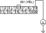
Is there battery voltage?
YES - Go to step 13.
NO - Repair open in the wire between the EPS control unit connector C (20P) and No. 10 (7.5A) fuse.
- Measure the voltage between the EPS control unit connector A (2P) terminal No. 1 and body ground.
EPS CONTROL UNIT CONNECTOR A (2P)

Is there battery voltage?
YES - Go to step 14.
NO - Check for a blown No. 18 (60A) fuse in the under-hood fuse/relay box or open/short in the WHT/BLU wire between the under-hood fuse/relay box and the EPS control unit.
- Turn the ignition switch OFF.
- Reconnect the EPS control unit connector A (2P).
- Turn the ignition switch ON (II).
- Measure the voltage between the EPS control unit connector C (20P) terminal No. 8 and body ground.
EPS CONTROL UNIT CONNECTOR C (20P)
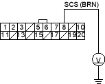
Is there battery voltage?
YES - Check for loose EPS control unit connectors. If necessary, substitute a known-good EPS control unit and retest.
NO - Repair short to ground in the BRN wire between the data link connector (KB, KE, KG, TR models: service check connector) and the EPS control unit.

