- Raise the vehicle and make sure it is securely supported.
- Check for a bent or deformed wheel.
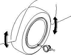
- Set up the dial gauge as shown and measure the axial runout by turning the wheel.
Front and Rear Wheel axial runout:
Standard:
Aluminium Wheel: |
0 – 0.7 mm (0 – 0.03 in.) |
Steel Wheel: |
0 – 1.0 mm (0 – 0.04 in.) |
Service limit: |
2.0 mm (0.08 in.) |
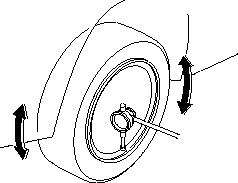
- Reset the dial gauge to the position shown and measure the radial runout.
Front and Rear Wheel radial runout:
Standard:
Aluminium Wheel: |
0 – 0.7 mm (0 – 0.03 in.) |
Steel Wheel: |
0 – 1.0 mm (0 – 0.04 in.) |
Service limit: |
1.5 mm (0.06 in.) |
- If the wheel runout is not within the specification, check the wheel bearing end play (see page 18-8).
- If the bearing end play is within the specification but the wheel runout is more than the service limit, replace the wheel.
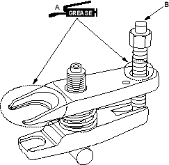
Ball joint remover, 28 mm, 07MAC-SL00200
NOTE: Always use a ball joint remover to disconnect a ball joint. Do not strike the housing or any other part of the ball joint connection to disconnect it.
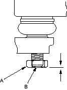
- Install a hex nut (A) onto the threads of the ball joint (B). Be sure the nut is flush with the ball joint pin end to prevent damage to the thread end of the ball joint pin.
- Apply grease to the special tool on the areas shown (A). This will ease installation of the tool and prevent damage to the pressure bolt (B) threads.