Special Tools Required
- Handle Driver, 07749-0010000
- Driver Attachment, 96 mm, 07948-SB00101
- Apply engine oil to the main bearings and rod bearings.
- Install the bearing halves in the cylinder block and connecting rods.
- Hold the crankshaft so rod journal No. 2 and rod journal No. 3 are straight up and lower the crankshaft into the block.
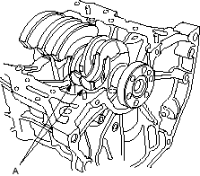
- Install the thrust washers (A) on both edges of the No. 4 main bearing recess.
- Apply engine oil to the threads of the connecting rod bolts.
- Seat the rod journals into connecting rod No. 1 and connecting rod No. 4. Install the caps and nuts finger tight. Install the cap so the bearing recess is on the same side as the recess in the rod.
- Rotate the crankshaft clockwise and seat the journals into connecting rod No. 2 and connecting rod No. 3. Install the connecting rod cap and bolts finger tight.
- Check the connecting rod bearing clearance with plastigage (see page 7-9).
- Tighten the connecting rod bolts to 32 Nm (3.3 kgf/m, 24 lbf/ft).
- Check the main bearing clearance with plastigage (see page 7-7).
- Install the bearing cap bridge. Coat the bolt threads with engine oil.
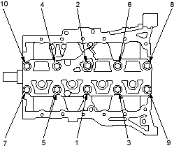
- Torque the cylinder head bolts sequentially in 2 steps.
1st step torque: 25 Nm (2.5 kgf/m, 18 lbf/ft)
2nd step torque:
D14Z5, D15Y2, D15Y3, D15Y4, D15Y5, D15Y6
| Engines: | 44 Nm (4.5 kgf/m, 33 lbf/ft) |
D16V2, D16W7, D16W8, D17Z1, D17Z2, D17Z3, D17A1, D17A2, D17A5 engines:
| 51 Nm (5.2 kgf/m, 38 lbf/ft) |
NOTE: Whenever any crankshaft or connecting rod bearing is replaced, it is necessary after reassembly to run the engine at idling speed until it reaches normal operating temperature, then continue to run it for approximately 15 minutes.
BEARING CAP BOLTS TIGHTENING SEQUENCE: